XCMH2102L8
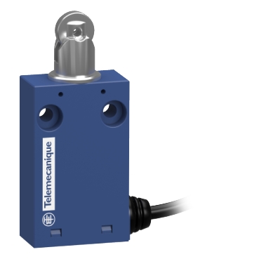
XCMH Limit Switches Miniature Plastic Metal Roller Plunger NC + NO Snap L8

Commercialized
Expand all
Datasheet
Range of product
Telemecanique Limit switches XC Standard
Series name
Standard format
Product or component type
Limit switch
Device short name
XCMH
Sensor design
Miniature
Body type
Fixed
Head type
Plunger head
Material
Plastic
Body material
Plastic
Head material
Zamak
Fixing mode
By the body
Movement of operating head
Linear
Type of operator
Spring return roller plunger metal
Type of approach
Lateral approach, 2 directions
Number of poles
2
Contacts type and composition
1 NC + 1 NO
Contact operation
Snap action
Switch actuation
By 30° cam
Electrical connection
Fixed cable
Cable length
8 m
Cable composition
4 x 0.34 mm²
Wire insulation material
PvR
Contacts insulation form
Zb
Positive opening
With
Positive opening minimum force
35 N
Minimum force for tripping
7 N
Maximum actuation speed
0.5 m/s
Contact code designation
C300, AC-15 (Ue = 240 V), Ie = 0.75 A conforming to IEC 60947-5-1 appendix A
R300, DC-13 (Ue = 250 V), Ie = 0.1 A conforming to IEC 60947-5-1 appendix A
R300, DC-13 (Ue = 250 V), Ie = 0.1 A conforming to IEC 60947-5-1 appendix A
[Ui] rated insulation voltage
300 V (pollution degree 3) conforming to UL 508
300 V (pollution degree 3) conforming to IEC 60947-5-1
300 V (pollution degree 3) conforming to CSA C22.2 No 14
300 V (pollution degree 3) conforming to IEC 60947-5-1
300 V (pollution degree 3) conforming to CSA C22.2 No 14
Maximum resistance across terminals
25 MOhm conforming to IEC 60255-7 category 3
[Uimp] rated impulse withstand voltage
4 kV conforming to IEC 60664
4 kV conforming to IEC 60947-1
4 kV conforming to IEC 60947-1
Short-circuit protection
6 A cartridge fuse, type gG
Electrical durability
5000000 cycles, DC-13, 120 V, 1 W, operating rate <60 cyc/mn, load factor: 0.5 conforming to IEC 60947-5-1 appendix C
5000000 cycles, DC-13, 24 V, 3 W, operating rate <60 cyc/mn, load factor: 0.5 conforming to IEC 60947-5-1 appendix C
5000000 cycles, DC-13, 48 V, 2 W, operating rate <60 cyc/mn, load factor: 0.5 conforming to IEC 60947-5-1 appendix C
5000000 cycles, DC-13, 24 V, 3 W, operating rate <60 cyc/mn, load factor: 0.5 conforming to IEC 60947-5-1 appendix C
5000000 cycles, DC-13, 48 V, 2 W, operating rate <60 cyc/mn, load factor: 0.5 conforming to IEC 60947-5-1 appendix C
Mechanical durability
5000000 cycles
Width
30 mm
Height
70.4 mm
Depth
16 mm
Shock resistance
25 gn for 18 ms conforming to IEC 60068-2-27
Vibration resistance
5 gn (f= 10…500 Hz) conforming to IEC 60068-2-6
IP degree of protection
IP66 conforming to IEC 60529
IP67 conforming to IEC 60529
IP67 conforming to IEC 60529
IK degree of protection
IK04 conforming to IEC 62262
Electrical shock protection class
Class II conforming to IEC 61140
Class II conforming to NF C 20-030
Class II conforming to NF C 20-030
Ambient air temperature for operation
-25…70 °C
Ambient air temperature for storage
-40…70 °C
Protective treatment
TC
Product certifications
CSA
UL
CCC
UL
CCC
Standards
CSA C22.2 No 14
IEC 60947-5-1
UL 508
IEC 60204-1
IEC 60947-5-1
UL 508
IEC 60204-1
Unit Type of Package 1
PCE
Number of Units in Package 1
1
Package 1 Height
1.6 cm
Package 1 Width
20 cm
Package 1 Length
25 cm
Package 1 Weight
269 g
Unit Type of Package 2
S03
Number of Units in Package 2
14
Package 2 Height
30 cm
Package 2 Width
30 cm
Package 2 Length
40 cm
Package 2 Weight
8.372 kg
REACh Regulation
EU RoHS Directive
Pro-active compliance (Product out of EU RoHS legal scope)
Mercury free
Yes
RoHS exemption information
WEEE
The product must be disposed on European Union markets following specific waste collection and never end up in rubbish bins
California proposition 65
WARNING: This product can expose you to chemicals including: Diisononyl phthalate (DINP), which is known to the State of California to cause cancer, and Di-isodecyl phthalate (DIDP), which is known to the State of California to cause birth defects or other reproductive harm. For more information go to www.P65Warnings.ca.gov
Warranty
18 months
Expand all
Technical Drawings
Dimensions
Dimensions
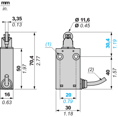
(1) 2 fixing holes Ø 4.2 mm (0.16 in.), counterbored Ø 8 mm by 4 mm deep (counterbored Ø 0.32 in. by 0.16 in. deep).
(2) Cable external diameter: 4.2 mm (0.16 in.)
Mounting and Clearance
Mounting and Clearance
Mounting: distance required for connection

d : min.15 mm/min.0.59 in.
Mounting and Clearance
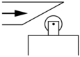
Sweep of Connecting Cable
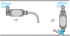
(1) : Recommended
(2) : To be avoided
Mounting and Clearance
Mounting with Spacers
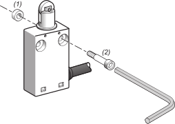
(1) : 2 spacers supplied with the switch
(2) : 2 screws Ø 4mm (not included)
Wiring diagram
Wiring diagram
2-pole NC + NO snap action
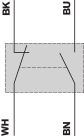
(BK) Black
(WH) White
(BN) Brown
(BU) Blue
Characteristics of Actuation
Switch Actuation by 30° Cam
Functional Diagram
Functional Diagram
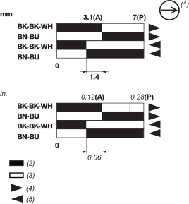
(P) Positive opening point
(A) Cam displacement
(1) NC contact with positive opening operation
(2) Closed
(3) Open
(4) Tripping
(5) Resetting
(BK) Black
(BK-WH) Black White
(BN) Brown
(BU) Blue
Expand all
Documents & Downloads
Document name
Date
Size
Document name
Date
Size
11/29/2023
61.8 MB
11/23/2023
62.3 MB
Document name
Date
Size
11/22/2023
427.1 kB
1/28/2024
530.3 kB
11/22/2023
195.3 kB
11/22/2023
195.3 kB
Document name
Date
Size
Expand all
Related products & accessoires
XCMH2102L9
XCMH Limit Switches Miniature Plastic Metal Roller Plunger NC + NO Snap L9
XCMH2102L1
XCMH Limit Switches Miniature Plastic Metal Roller Plunger NC + NO Snap L1
XCMH2102L2
XCMH Limit Switches Miniature Plastic Metal Roller Plunger NC + NO Snap L2
XCMH2102L3
XCMH Limit Switches Miniature Plastic Metal Roller Plunger NC + NO Snap L3
XCMH2102L5
XCMH Limit Switches Miniature Plastic Metal Roller Plunger NC + NO Snap L5
XCMH2102L6
XCMH Limit Switches Miniature Plastic Metal Roller Plunger NC + NO Snap L6
XCMH2102L7
XCMH Limit Switches Miniature Plastic Metal Roller Plunger NC + NO Snap L7
Back to top