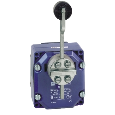
XCRA12
Limit switch, Limit switches XC Standard, XCR, thermoplastic spring return roller lever, 2X(1NC+NO)

Commercialized

Expand all
Datasheet
Range of product
OsiSense XC
Series name
Special format
Product or component type
Limit switch
Product specific application
For hoisting and mechanical handling applications
Device short name
XCR
Sensor design
-
Body type
Fixed
Head type
Rotary head
Material
Metal
Fixing mode
By the body
Movement of operating head
Rotary
Type of operator
Spring return roller lever thermoplastic -
Type of approach
Lateral approach, 2 directions
Electrical connection
Screw-clamp terminals, clamping capacity: 1 x 0.34...2 x 1.5 mm²
Number of poles
4
Contacts type and composition
2 x (1 NC + 1 NO)
Contact operation
Snap action
Contact block per direction [control circuit]
2 per direction
Positive opening
With
Body material
Zinc alloy
Switch actuation
By any moving part
Cable entry
1 entry tapped for Pg 13.5 cable gland, cable outer diameter: 9…12 mm conforming to NF C 68-300
Contacts insulation form
Zb
Number of steps
1
Positive opening minimum torque
0.75 N.m
Minimum torque for tripping
0.45 N.m
Minimum actuation speed
0.01 m/min
Maximum actuation speed
1.5 m/s
Maximum displacement angle
55 °
-55 °
-55 °
Contact code designation
A300, AC-15 (Ue = 240 V), Ie = 3 A conforming to IEC 60947-5-1 appendix A
Q300, DC-13 (Ue = 250 V), Ie = 0.27 A conforming to IEC 60947-5-1 appendix A
Q300, DC-13 (Ue = 250 V), Ie = 0.27 A conforming to IEC 60947-5-1 appendix A
[Ui] rated insulation voltage
300 V conforming to UL 508
500 V (pollution degree 3) conforming to IEC 60947-1
500 V (pollution degree 3) conforming to VDE 0110
300 V conforming to CSA C22.2 No 14
500 V (pollution degree 3) conforming to IEC 60947-1
500 V (pollution degree 3) conforming to VDE 0110
300 V conforming to CSA C22.2 No 14
Maximum resistance across terminals
25 MOhm conforming to IEC 60255-7 category 3
[Uimp] rated impulse withstand voltage
6 kV conforming to IEC 60664
6 kV conforming to IEC 60947-1
6 kV conforming to IEC 60947-1
Short-circuit protection
10 A cartridge fuse, type gG
Electrical durability
5000000 cycles, DC-13, inductive load type, 120 V, 4 W, operating rate <60 cyc/mn, load factor: 0.5 conforming to IEC 60947-5-1 appendix C
5000000 cycles, DC-13, inductive load type, 24 V, 7 W, operating rate <60 cyc/mn, load factor: 0.5 conforming to IEC 60947-5-1 appendix C
5000000 cycles, DC-13, inductive load type, 48 V, 10 W, operating rate <60 cyc/mn, load factor: 0.5 conforming to IEC 60947-5-1 appendix C
5000000 cycles, DC-13, inductive load type, 24 V, 7 W, operating rate <60 cyc/mn, load factor: 0.5 conforming to IEC 60947-5-1 appendix C
5000000 cycles, DC-13, inductive load type, 48 V, 10 W, operating rate <60 cyc/mn, load factor: 0.5 conforming to IEC 60947-5-1 appendix C
Mechanical durability
10000000 cycles
Width
85 mm
Height
95 mm
Depth
75 mm
Net weight
1.145 kg
Terminals description ISO n°1
(13-14)NO
(21-22)NC
(21-22)NC
Shock resistance
68 gn conforming to IEC 60068-2-27
Vibration resistance
9 gn (f= 10…500 Hz) conforming to IEC 60068-2-6
IP degree of protection
IP54 conforming to IEC 60529
Overvoltage category
Class I conforming to IEC 61140
Class I conforming to NF C 20-030
Class I conforming to NF C 20-030
Ambient air temperature for operation
-25…70 °C
Ambient air temperature for storage
-40…70 °C
Protective treatment
TC
Product certifications
CCC
CSA
CSA
Standards
IEC 60947-5-1
NF C 79-130
CSA C22.2 No 14
IEC 60204-1
IEC 60947-5-1
IEC 60204-1
NF C 79-130
CSA C22.2 No 14
IEC 60204-1
IEC 60947-5-1
IEC 60204-1
Unit Type of Package 1
PCE
Number of Units in Package 1
1
Package 1 Height
8.400 cm
Package 1 Width
10.400 cm
Package 1 Length
20.600 cm
Package 1 Weight
1.055 kg
Unit Type of Package 2
S02
Number of Units in Package 2
5
Package 2 Height
15.000 cm
Package 2 Width
30.000 cm
Package 2 Length
40.000 cm
Package 2 Weight
5.577 kg
Sustainable offer status
Green Premium product
REACh Regulation
EU RoHS Directive
Pro-active compliance (Product out of EU RoHS legal scope)
Mercury free
Yes
RoHS exemption information
Circularity Profile
No need of specific recycling operations
California proposition 65
WARNING: This product can expose you to chemicals including: Diisononyl phthalate (DINP), which is known to the State of California to cause cancer, and Di-isodecyl phthalate (DIDP), which is known to the State of California to cause birth defects or other reproductive harm. For more information go to www.P65Warnings.ca.gov
Warranty
18 months
Expand all
Technical Drawings
Dimensions
- (1) 1 tapped entry for n° 13 cable gland.
- (2) Rod + roller length: 160 mm.
Wiring Diagram
Two 2-pole NC + NO Snap Action
- (A) 1 contact
- (B) 2 contact
Functionnal Diagram
- (P) Positive opening point
- (A) 1st contact
- (B) 2nd contact
- (1) NC contact with positive opening operation
- (2) Closed
- (3) Open
- (4) Tripping
- (5) Resetting
Expand all
Documents & Downloads
Document name
Date
Size
11/23/2023
1.2 MB
11/23/2023
473.4 kB
11/23/2023
1.2 MB
Document name
Date
Size
11/23/2023
11.9 MB
11/23/2023
11.9 MB
11/29/2023
12.0 MB
11/29/2023
12.0 MB
Document name
Date
Size
11/29/2023
645.5 kB
11/23/2023
195.3 kB
11/23/2023
195.3 kB
Document name
Date
Size
11/23/2023
1.0 MB
Expand all
Related products & accessoires
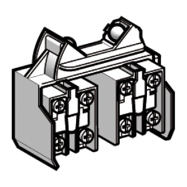
XCRZ12
Limit switch contact block with mounting plate, Limit switches XC Standard, XCRZ, 2X(1NO+NC), snap action
XCRZ15
Limit switch contact block with mounting plate, Limit switches XC Standard, XCRZ, 2X(1NO+NC), slow break, break before make
XCRZ09
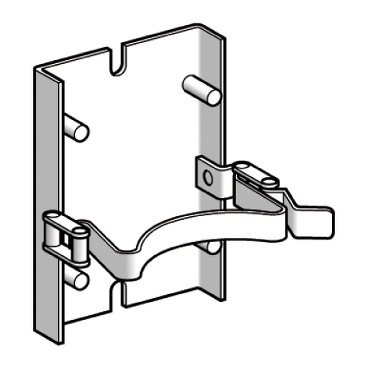
Limit switches XC Standard, quick fixing release bracket, quick fixing release bracket, for XCRA,B, E, F

XCRZ03
Limit switch lever, Limit switches XC Standard, XCRZ, steel square rod 6 mm, L=200 mm
XCRZ04
Limit switch lever, Limit switches XC Standard, XCRZ, steel square rod 6 mm, L=300 mm
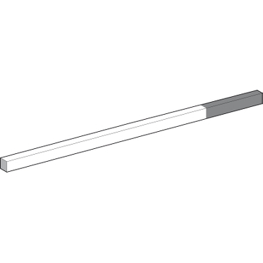
XCRZ03R
Limit switch lever, Limit switches XC Standard, XCRZ, steel square rod 6 mm, L=200 mm with red end
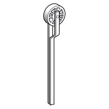
XCRZ02
Limit switch lever, Limit switches XC Standard, XCRZ, thermoplastic roller for
XCRZ05
Limit switch lever, Limit switches XC Special, XCRZ, large thermoplastic roller
Back to top