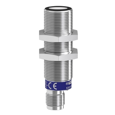
XXS18S1AM12
Ultrasonic sensors XX, ultrasonic sensor cylindrical M18, Sn=1 m, analog 4 20 mA, SYNC, connector M12

Commercialized

Expand all
Datasheet
Range of product
Telemecanique Ultrasonic sensors XX
Sensor type
Ultrasonic sensor
Series name
General purpose
Sensor name
XXS
Sensor design
Cylindrical M18
Detection system
Diffuse
[Sn] nominal sensing distance
1 m adjustable with remote teach push-button
1 m software with kit
1 m software with kit
Material
Metal
Type of output signal
Analogue
Wiring technique
5-wire
Analogue output function
4...20 mA
[Us] rated supply voltage
12...24 V DC with reverse polarity protection
Electrical connection
Male connector M12 5 pins
[Sd] sensing range
0.105…1 m
IP degree of protection
IP65 conforming to IEC 60529
IP67
IP67
Enclosure material
Stainless steel 316L
Front material
Epoxy
Rubber
Resin
Rubber
Resin
Supply voltage limits
10…30 V DC
Function available
With synchronisation mode
Software configurable
Software configurable
[Sa] assured operating distance
0.105…1 m (teach mode)
Blind zone
105 mm
Transmission frequency
200 kHz
Repeat accuracy
0.1 %
Deviation angle from 90° of object to be detected
-10…10 °
Minimum size of detected object
Cylinder diameter 1 mm at 600 mm
Status LED
Output state: 1 LED (yellow)
Echo state: 1 LED (green)
Echo state: 1 LED (green)
Current consumption
30 mA
Maximum switching capacity
250 Ohm with 12 V DC overload and short-circuit protection
850 Ohm with 24 V DC
850 Ohm with 24 V DC
Setting-up
Teach mode
Configurator software
Configurator software
Maximum delay first up
180 ms
Maximum delay recovery
100 ms
Marking
CE
Threaded length
45 mm
Height
18 mm
Width
18 mm
Depth
64 mm
Net weight
0.05 kg
Standards
IEC 60947-5-2
CSA C22.2 No 14
UL 508
CSA C22.2 No 14
UL 508
Product certifications
cULus
E2
RCM
Ecolab
E2
RCM
Ecolab
Ambient air temperature for operation
-25…70 °C
Ambient air temperature for storage
-40…80 °C
Vibration resistance
+/-1 mm conforming to IEC 60068-2-6 (f = 10…55 Hz)
Shock resistance
30 gn in all 3 axes for 11 ms conforming to IEC 60068-2-27
Resistance to electrostatic discharge
8 kV level 4 conforming to IEC 61000-4-2
Resistance to electromagnetic fields
10 V/m level 3 conforming to IEC 61000-4-3
Resistance to fast transients
1 kV level 3 conforming to IEC 61000-4-4
Unit Type of Package 1
PCE
Number of Units in Package 1
1
Package 1 Height
4.1 cm
Package 1 Width
6.4 cm
Package 1 Length
9.4 cm
Package 1 Weight
49.986 g
Sustainable offer status
Green Premium product
REACh Regulation
EU RoHS Directive
Pro-active compliance (Product out of EU RoHS legal scope)
Mercury free
Yes
RoHS exemption information
Circularity Profile
No need of specific recycling operations
California proposition 65
WARNING: This product can expose you to chemicals including: Diisononyl phthalate (DINP), which is known to the State of California to cause cancer, and Di-isodecyl phthalate (DIDP), which is known to the State of California to cause birth defects or other reproductive harm. For more information go to www.P65Warnings.ca.gov
Expand all
Technical Drawings
Dimensions
Connections
Connector Wiring
- (1) : Synchronization
- (2) : External setting pushbutton or XXZPB100 remote teach pushbutton.
| Pin number | Wire color | Description |
|---|---|---|
| 1 | BN: Brown | +12…24VDC |
| 2 | WH: White | Input teach |
| 3 | BU: Blue | 0 VDC |
| 4 | BK: Black | Output |
| 5 | GY: Grey | Synchronization |
Connections
Wiring Scheme
- (1) : Synchronization
- (2) : External setting pushbutton or XXZPB100 remote teach pushbutton.
- (1) : Synchronization
Connections
Wiring for the Synchronization Function (Side by Side Application)
- (1) : Synchronization
- (2) : External setting pushbutton or XXZPB100 remote teach pushbutton.
- (1) : Synchronization
- BN : Brown
- WH : White
- BU : Blue
- BK : Black
- GY : Grey
NB: To enable synchronization between several sensors, all of the wires of pin no.5 (Grey) must be electrically connected together.A maximum of 8 sensors can be synchronized. To enable “Multiplexer” function for the sensors, use the XX Configuration Software.Without synchronization or multiplexing, the sensors must be at least 50 cm away from each other in order to avoid mutual interference.
Performance Curves
Detection Curve with 100 x 100 mm / 3.94 x 3.94 in. Square Target
- (x) Target distance
- (y) Detection limit
- (1) : Blind zone: 105 mm
- (2) : Sn max.
- (3) : 100 x 100 mm / 3.94 x 3.94 in. stainless steel plate
Performance Curves
Detection Curve with Round Bar
- (x) Target distance
- (y) Detection limit
- (1) : Blind zone: 105 mm
- (2) : Sn max.
- (3) : 100 x 100 mm / 3.94 x 3.94 in. stainless steel plate
- (x) Target distance
- (y) Detection limit
- (1) : Blind zone: 105 mm
- (2) : Sn max.
- (3) : Ø 10 mm / 0.394 in. stainless steel cylinder
- (4) : Ø 25 mm / 0.984 in. stainless steel cylinder
Operating Diagram
Near and Far Limits Setting with Teach Procedure
- (1) : Blind zone
- (2) : Near limit
- (3) : Sensing window
- (4) : Far limit
- (5) : Sn max
- (6) : Inverse
- (7) : Direct
- (8) : ON
- (9) : OFF
- GN : Green LED
- YE : Yellow LED
Expand all
Documents & Downloads
Document name
Date
Size
11/22/2023
5.9 MB
11/22/2023
5.9 MB
Document name
Date
Size
Document name
Date
Size
11/23/2023
17.9 MB
11/23/2023
18.1 MB
11/23/2023
17.9 MB
11/23/2023
18.0 MB
Document name
Date
Size
11/28/2023
195.3 kB
11/28/2023
195.3 kB
Document name
Date
Size
11/22/2023
1.6 MB
Expand all
Related products & accessoires

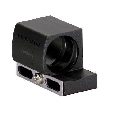
XSZB118
Inductive proximity sensors XS, accessory for sensor, Ø 18 mm, fixing clamp, plastic, with indexing
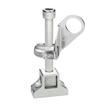
XUZ2001
Photoelectric sensors XU, accessory for sensor, 3D fixing kit, M12 rod

XUZ2003
Photoelectric sensors XU, accessory for sensor, 3D fixing kit, support for M12 rod

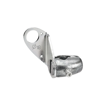
XUZA118
90° fixing bracket, Photoelectric sensors XU, accessory for sensor, Ø 18 mm, stainless steel
XUZB2003
Photoelectric sensors XU, accessory for sensor, 3D fixing kit, bracket with ball joint, Ø 18 mm
XXZB118
Low temperature operation accessory, Mounting for OsiSense XX M18
XZCC12FCM40B
Female, M12, 4 pin, elbowed connector, cable gland Pg 7
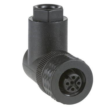
XZCC12FCP40B
Female, M12, 4 pin, elbowed connector, cable gland Pg 7
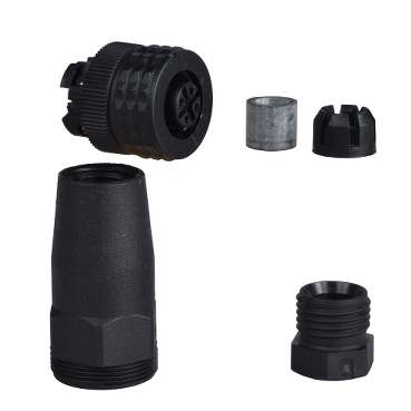
XZCC12FDM40B
Female, M12, 4 pin, straight connector, cable gland Pg 7
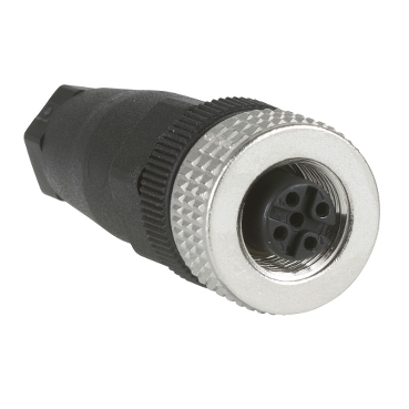
XZCC12FDP40B
Female, M12, 4 pin, straight connector, cable gland Pg 7
XZCP1141L2
Pre wired connectors XZ, straight female, M12, 4 pins, cable PUR 2 m
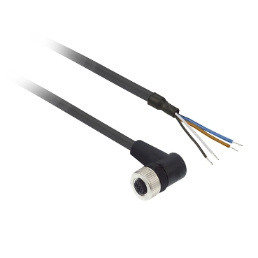
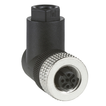
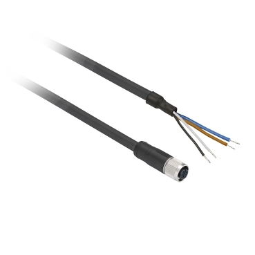
XZCP1241L2
Pre wired connectors XZ, elbowed female, M12, 4 pins, cable PUR 2 m
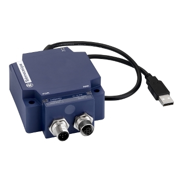
XXZBOX01
Ultrasonic sensor configuration interface
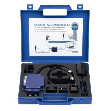
XXZKIT01
Ultrasonic sensor configuration kit
Back to top