Expand all
Datasheet
1 m software with kit
IP67
Rubber
Resin
Software configurable
Echo state: 1 LED (green)
Configurator software
CSA C22.2 No 14
UL 508
E2
RCM
Ecolab
Expand all
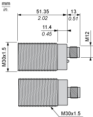
Technical Drawings
Dimensions
Connections
Connector Wiring
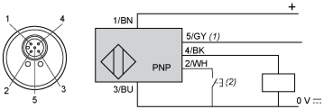
- (1) : Synchronization
- (2) : External setting pushbutton or XXZPB100 remote teach pushbutton.
| Pin number | Wire color | Description |
|---|---|---|
| 1 | BN: Brown | +12…24VDC |
| 2 | WH: White | Input teach |
| 3 | BU: Blue | 0 VDC |
| 4 | BK: Black | Output |
| 5 | GY: Grey | Synchronization |
Connections
Wiring Scheme. Digital Output (NO or NC)

- (1) : Synchronization
- (2) : External setting pushbutton or XXZPB100 remote teach pushbutton.
- (1) : Synchronization
Connections
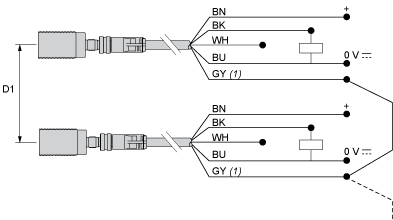
Wiring for the Synchronization Function (Side by Side Application)
- (1) : Synchronization
- (2) : External setting pushbutton or XXZPB100 remote teach pushbutton.
- (1) : Synchronization
- (1) : Synchronization
- D1 : 1/8 Sn
- BN : Brown
- WH : White
- BU : Blue
- BK : Black
- GY : Grey
NOTE: Up to 8 sensors can be synchronized to operate side by side by electrically connecting all pin no.5 (grey) wires together.
To synchronize more than 8 sensors, a PLC output can be used (the pins no.5 must be simultaneously driven by the rising edge of a pulse).
Performance Curves
Detection Curve with 100 x 100 mm / 3.94 x 3.94 inches Square Target
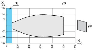
- (X) : Target distance
- (Y) : Detection limit
- (1) : Blind zone: 105 mm / 4.13 inches
- (2) : Sn max.
- (3) : 100 x 100 mm / 3.94 x 3.94 inches stainless steel plate
Performance Curves
Detection Curve with Round Bar
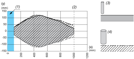
- (X) : Target distance
- (Y) : Detection limit
- (1) : Blind zone: 105 mm / 4.13 inches
- (2) : Sn max.
- (3) : 100 x 100 mm / 3.94 x 3.94 inches stainless steel plate
- (X) : Target distance
- (Y) : Detection limit
- (1) : Blind zone: 105 mm / 4.13 inches
- (2) : Sn max.
- (3) : Ø 10 mm / 0.394 inches stainless steel cylinder
- (4) : Ø 25 mm / 0.984 inches stainless steel cylinder
Expand all
Documents & Downloads
Document name
Date
Size
11/22/2023
11.7 MB
11/22/2023
11.7 MB
Document name
Date
Size
11/22/2023
5.7 MB
Document name
Date
Size
11/23/2023
17.9 MB
11/23/2023
18.1 MB
11/23/2023
17.9 MB
11/23/2023
18.0 MB
Document name
Date
Size
11/29/2023
195.3 kB
11/22/2023
195.3 kB
Document name
Date
Size
11/22/2023
5.5 kB
Document name
Date
Size
11/22/2023
2.8 MB
Expand all
Related products & accessoires
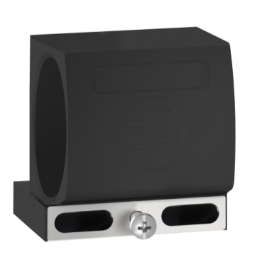
Mounting accessory for OsiSense XX M30
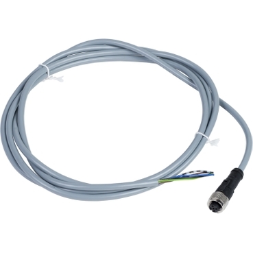
Pre wired connectors XZ, straight female, M12, 5 pins, cable PVC 2 m
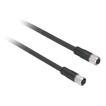
Pre wired connectors XZ, straight female, M12, 5 pins, cable PVC 2 m
Back to top

