ZB5AP6S
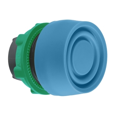
Head for non illuminated push button, Harmony XB5, XB4, blue flush pushbutton Ø22 mm spring return unmarked

Commercialized
Expand all
Datasheet
Range of product
Harmony XB5
Product or component type
Head for non-illuminated push-button
Device short name
ZB5
Product compatibility
Legend holder
Bezel material
Dark grey plastic
Mounting diameter
22 mm
Head type
Standard
Sale per indivisible quantity
1
Shape of signaling unit head
Round
Type of operator
spring return
Operator profile
Blue flush, unmarked
Operator additional information
Coloured boot
CAD overall width
30 mm
CAD overall height
30 mm
CAD overall depth
33 mm
Net weight
0.021 kg
Mechanical durability
10000000 cycles
Station name
XALD 1...5 cut-outs
XALK 2...5 cut-outs
XALK 2...5 cut-outs
Electrical composition code
C1 for <9 contacts using single blocks in front mounting
C2 for <9 contacts using single and double blocks in front mounting
C11 for <3 contacts using single blocks in front mounting
C15 for <1 contacts using single blocks in front mounting
SF1 for <3 contacts using single blocks in front mounting
SR1 for <3 contacts using single blocks in rear mounting
C2 for <9 contacts using single and double blocks in front mounting
C11 for <3 contacts using single blocks in front mounting
C15 for <1 contacts using single blocks in front mounting
SF1 for <3 contacts using single blocks in front mounting
SR1 for <3 contacts using single blocks in rear mounting
Device presentation
Basic element
Protective treatment
TH
Ambient air temperature for storage
-40…70 °C
Ambient air temperature for operation
-40…70 °C
Overvoltage category
Class II conforming to IEC 60536
IP degree of protection
IP66 conforming to IEC 60529
IP67 conforming to IEC 60529
IP69 conforming to IEC 60529
IP69K conforming to ISO 20653
IP67 conforming to IEC 60529
IP69 conforming to IEC 60529
IP69K conforming to ISO 20653
NEMA degree of protection
NEMA 13
NEMA 4X
NEMA 4X
Resistance to high pressure washer
7000000 Pa at 55 °C, distance : 0.1 m
IK degree of protection
IK03 conforming to IEC 50102
Standards
JIS C8201-5-1
CSA C22.2 No 14
EN/IEC 60947-5-4
EN/IEC 60947-5-1
EN/IEC 60947-1
UL 508
JIS C8201-1
CSA C22.2 No 14
EN/IEC 60947-5-4
EN/IEC 60947-5-1
EN/IEC 60947-1
UL 508
JIS C8201-1
Product certifications
LROS (Lloyds register of shipping)
UL listed
DNV
CSA
BV
GL
UL listed
DNV
CSA
BV
GL
Shock resistance
30 gn (duration = 18 ms) for half sine wave acceleration conforming to IEC 60068-2-27
50 gn (duration = 11 ms) for half sine wave acceleration conforming to IEC 60068-2-27
50 gn (duration = 11 ms) for half sine wave acceleration conforming to IEC 60068-2-27
Vibration resistance
5 gn (f= 2…500 Hz) conforming to IEC 60068-2-6
Unit Type of Package 1
PCE
Number of Units in Package 1
1
Package 1 Height
5.4 cm
Package 1 Width
3.4 cm
Package 1 Length
4.5 cm
Package 1 Weight
19.0 g
Unit Type of Package 2
S01
Number of Units in Package 2
75
Package 2 Height
15.0 cm
Package 2 Width
15.0 cm
Package 2 Length
40.0 cm
Package 2 Weight
1.65 kg
REACh Regulation
EU RoHS Directive
Pro-active compliance (Product out of EU RoHS legal scope)
Mercury free
Yes
China RoHS Regulation
RoHS exemption information
California proposition 65
WARNING: This product can expose you to chemicals including: Di-isodecyl phthalate (DIDP), which is known to the State of California to cause birth defects or other reproductive harm. For more information go to www.P65Warnings.ca.gov
Warranty
18 months
Expand all
Technical Drawings
Dimensions
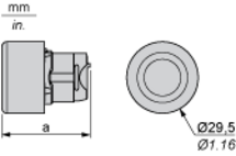
| a in mm | a in in. | |
|---|---|---|
| 36.5 | 1.44 | |
| 33 | 1.30 | |
| 32 | 1.26 | |
| 35 | 1.38 |
Panel Cut-out for Pushbuttons, Switches and Pilot Lights (Finished Holes, Ready for Installation)
Connection by Screw Clamp Terminals or Plug-in Connectors or on Printed Circuit Board
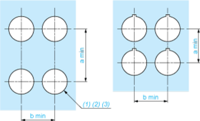
| Connections | a in mm | a in in. | b in mm | b in in. |
|---|---|---|---|---|
| By screw clamp terminals or plug-in connector | 40 | 1.57 | 30 | 1.18 |
| By Faston connectors | 45 | 1.77 | 32 | 1.26 |
| On printed circuit board | 30 | 1.18 | 30 | 1.18 |
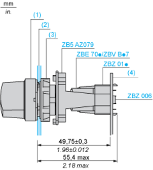
(1) Diameter on finished panel or support
(2) For selector switches and Emergency stop buttons, use of an anti-rotation plate type ZB5AZ902 is recommended.
+0.0160+0.40(3) Ø22.5 mm recommended (Ø22.3 ) / Ø0.89 in. recommended (Ø0.88 in. )
Panel Cut-out for Pushbuttons, Switches and Pilot Lights (Finished Holes, Ready for Installation)
Detail of Lug Recess
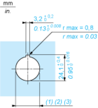
(1) Diameter on finished panel or support
(2) For selector switches and Emergency stop buttons, use of an anti-rotation plate type ZB5AZ902 is recommended.
+0.0160+0.40(3) Ø22.5 mm recommended (Ø22.3 ) / Ø0.89 in. recommended (Ø0.88 in. )
Pushbuttons, Switches and Pilot Lights for Printed Circuit Board Connection
Panel Cut-outs (Viewed from Installer’s Side)
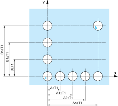
A: 30 mm min. / 1.18 in. min.
B: 40 mm min. / 1.57 in. min.
Pushbuttons, Switches and Pilot Lights for Printed Circuit Board Connection
Printed Circuit Board Cut-outs (Viewed from Electrical Block Side)
Printed Circuit Board Cut-outs (Viewed from Electrical Block Side)
Dimensions in mm
A: 30 mm min.
B: 40 mm min.
Dimensions in in.
A: 1.18 in. min.
B: 1.57 in. min.
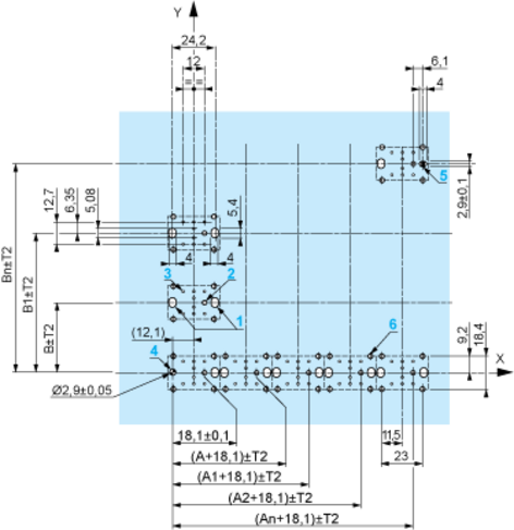
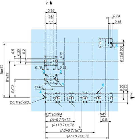
Pushbuttons, Switches and Pilot Lights for Printed Circuit Board Connection
The cumulative tolerance must not exceed 0.3 mm / 0.012 in.: T1 + T2 = 0.3 mm max.
Pushbuttons, Switches and Pilot Lights for Printed Circuit Board Connection
Installation Precautions
54baThe fixing centers marked and are diagonally opposed and must align with those marked and .
(1) Head ZB5AD•
(2) Panel
(2) Nut
(4) Printed circuit board
Pushbuttons, Switches and Pilot Lights for Printed Circuit Board Connection
Dimensions An + 18.1 relate to the Ø 2.4 mm ± 0.05 / 0.09 in. ± 0.002 holes for centring adapter ZBZ01•.
Electrical Composition Corresponding to Code C1
Electrical Composition Corresponding to Code C2

Electrical Composition Corresponding to Codes C9, C11, SF1 and SR1

Electrical Composition Corresponding to Code C15


1 N/O
1 N/C
1 N/O + N/C or 1 N/O + N/O or 1 N/C + N/C
Legend

Single contact
Legend

Double contact
Legend

Light block
Legend

Possible location
Expand all
Documents & Downloads
Document name
Date
Size
11/22/2023
10.1 MB
11/22/2023
22.2 MB
11/29/2023
4.5 MB
11/29/2023
4.6 MB
11/22/2023
10.0 MB
11/22/2023
30.2 MB
Document name
Date
Size
11/22/2023
581.8 kB
11/22/2023
812.1 kB
11/22/2023
520.6 kB
11/22/2023
198.7 kB
Document name
Date
Size
3/20/2024
245.8 kB
Document name
Date
Size
12/3/2023
195.3 kB
12/3/2023
195.3 kB
11/22/2023
195.3 kB
Document name
Date
Size
Expand all
Related products & accessoires
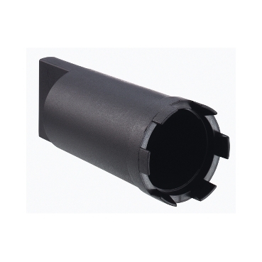
ZB5AZ905
Tightening tool for fixing nut, Harmony XB5, plastic, black
Back to top